1. 课程信息
- 实验地点:清水河校区KB239
- 实验时间:2021.04.9
- 实验时长: 3小时(4节课)
2. 实验要求
驱动板上数码管显示当前时间(包含时、分、秒)
①建议定义n个按键,如用于功能切换 (tab)、校时+1(up)及确认(ok)
②整点报时: 7:00~23:00间每个整点蜂鸣器响1s
思考(加分项):
1. 如何添加闹钟功能?
2. 如何添加定时器功能?
3. 设计模N计数器的测试向量集,撰写testbench进行验证测试
3. 设计与实现
3.1 电路功能说明
(包括各个模块功能、关键代码分析,可以使用文字、框图、功能表、状态图等进行说明)
3.1.1 顶层设计

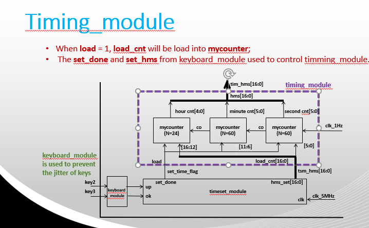
3.1.2 timing_module

接收PLL多次分频得到的1Hz时钟信号作为模块的时钟信号,设置17位数据用来存储当前时间([5:0]表示秒,[11:6]表示分,[16:12]表示小时),当秒达到59时,则下一次操作为秒位置0,同时分位加1,分钟与小时的关系依次类推。同时当load信号使能时,即设置时间功能打开时,数据位数据将被加载进来的数据覆盖。
// timing_module.v
`timescale 1ns / 1ps
//////////////////////////////////////////////////////////////////////////////////
// Company: UESTC
// Engineer: Qy_Ley
//
// Create Date: 2021/03/14 15:06:37
// Design Name: Digital Clock for EES331
// Module Name: timing_module
// Project Name: Digital Clock
// Target Devices: EES331
// Tool Versions: Vivado 18.3
// Description:
//
// Dependencies:
//
// Revision:
// Revision 0.01 – File Created
// Additional Comments:
//
//////////////////////////////////////////////////////////////////////////////////
module timing_module(
input i_clk_1Hz,
input i_load,
input i_rstn,
input i_ena,
input [16:0] i_load_hms, // [5:0] for sec, [11:6] for min, [16:12] for hour, BCD coding
output [16:0] o_hms // [5:0] for sec, [11:6] for min, [16:12] for hour, BCD coding
);
// wire m_co_sec, m_co_min; // Carry output from second & minute counter
reg ld;
reg [16:0] ld_cnt;
reg [4:0] hour_cnt;
reg [5:0] min_cnt,sec_cnt;
always @(posedge i_clk_1Hz) begin
ld <= i_load;
ld_cnt <= i_load_hms;
end //clock cross-domain buffer
always @(posedge i_clk_1Hz or negedge i_rstn) begin
if(!i_rstn) begin
hour_cnt <= 0;
min_cnt <= 0;
sec_cnt <= 0;
end
else if(ld) begin
{hour_cnt, min_cnt, sec_cnt} <= ld_cnt;
end
else if(i_ena) begin
if(sec_cnt == 6’d59) begin
sec_cnt <= 0;
if(min_cnt == 6’d59) begin
min_cnt <= 0;
if(hour_cnt == 5’d23) begin
hour_cnt <= 0;
end
else begin
hour_cnt <= hour_cnt+1;
end
end
else begin
min_cnt <= min_cnt+1;
end
end
else begin
sec_cnt <= sec_cnt+1;
end
end
end
/* Complete the counter for second, minute, hour */
assign o_hms = {hour_cnt, min_cnt, sec_cnt};
endmodule
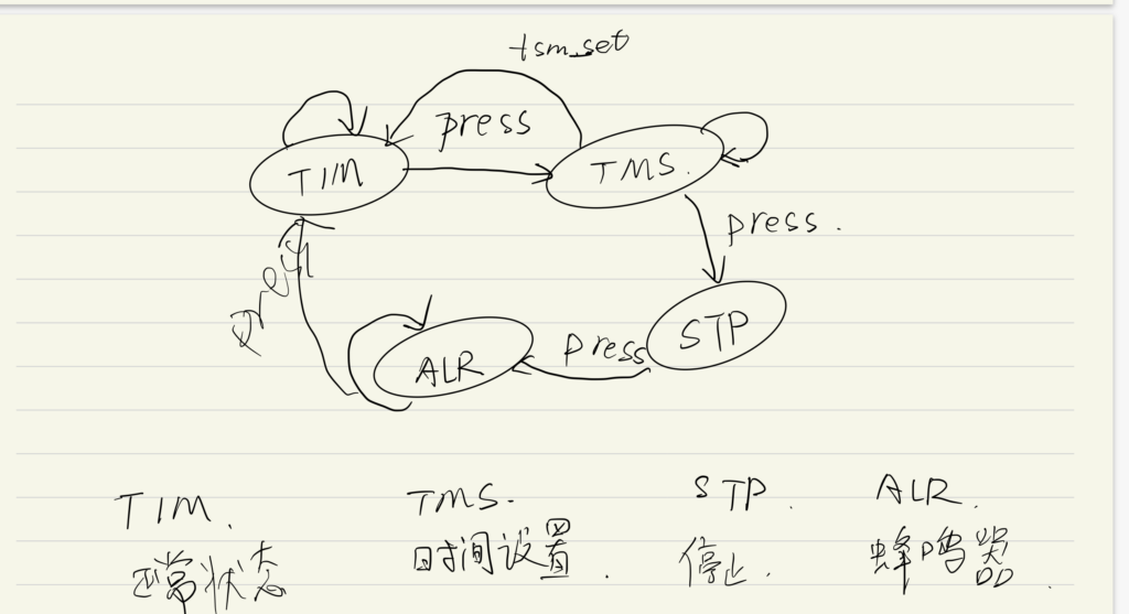
3.1.3 control_module
为系统控制的模块,采用有限状态机的描述方式,如图:

// control_module.v
`timescale 1ns / 1ps
//////////////////////////////////////////////////////////////////////////////////
// Company: UESTC
// Engineer: Qy_Ley
//
// Create Date: 2021/03/14 15:06:37
// Design Name: Digital Clock for EES331
// Module Name: control_module
// Project Name: Digital Clock
// Target Devices: EES331
// Tool Versions: Vivado 18.3
// Description:
//
// Dependencies:
//
// Revision:
// Revision 0.01 – File Created
// Additional Comments:
//
//////////////////////////////////////////////////////////////////////////////////
module control_module(
input i_clk_5MHz,
input i_rstn,
input i_ena,
input i_key_tab,
input i_tsm_set_flag, // time setting flag from Timeset module
input [16:0] i_tim_hms, // Timing module output
input [16:0] i_tsm_hms, // Timeset module ouput
input [16:0] i_swm_hms, // Stopwatch module output (reserved)
input [16:0] i_alm_hms, // Alarm module output (reserved)
output reg [16:0] o_disp_hms, // output to display module
output reg o_tsm_ena, // Timeset module enable
output reg o_alm_ena
);
reg i_key_tab_d1;
wire tab_press;
reg i_tsm_set_flag_d1;
wire i_tsm_set_done;
always @(posedge i_clk_5MHz) begin
i_key_tab_d1 <= i_key_tab;
i_tsm_set_flag_d1 <= i_tsm_set_flag;
end
assign tab_press = ^{i_key_tab_d1,i_key_tab}; // edge detect, =1 stand for tab key has been press down once
assign i_tsm_set_done = ({i_tsm_set_flag_d1,i_tsm_set_flag}==2’b10); // negtive edge detect , =1 stand for time set finish
// FSM Controller
parameter TIM=2’d0, TMS=2’d1, STP=2’d2, ALR=2’d3; // i.e. TIMing, TiMe Setting, SToP watch, ALaRm (4 funtion)
reg [1:0] state, next_state;
// Complete the State Tranfer Logic
always @(*) begin
case(state)
TIM: begin
//Example
if(tab_press) next_state = TMS;
else next_state = TIM;
end
TMS: begin
//your code here
if(tab_press) next_state = STP;
else if(i_tsm_set_done) next_state = TIM;
else next_state = TMS;
end
STP: begin
//your code here
if(tab_press) next_state = ALR;
else next_state = STP;
end
ALR: begin
//your code here
if(tab_press) next_state = TIM;
else next_state = ALR;
end
endcase
end
// State Transfer Block
always @(posedge i_clk_5MHz) begin
if(~i_rstn) state <= TIM;
else state <= next_state;
end
//Complete the Output of each State
always @(posedge i_clk_5MHz) begin
case(next_state)
TIM: begin
//your code here
o_tsm_ena <= 0;
o_alm_ena <= 0;
o_disp_hms <= i_tim_hms;
end
TMS: begin
//your code here
o_tsm_ena <= 1;
o_alm_ena <= 0;
o_disp_hms <= i_tsm_hms;
end
STP: begin
//your code here
o_tsm_ena <= 0;
o_alm_ena <= 0;
o_disp_hms <= i_swm_hms;
end
ALR: begin
//Example
o_tsm_ena <= 0;
o_alm_ena <= 1;
o_disp_hms <= i_alm_hms;
end
endcase
end
endmodule
3.2 电路接口定义

顶层的接口信号定义如下表 1所示。
表 1 顶层接口定义
| 信号名称 | 信号位宽(bit) | 信号方向(I/O) | 信号功能描述 |
| i_clk | 1 | I | 100MHz系统时钟 |
| i_rstn | 1 | I | 复位信号 |
| i_key1, i_key2, i_key3 | 1 | I | 3个按键输入 |
| o_seg, o_seg2 | 8 | O | 两个段选信号 |
| o_seg_cs | 6 | O | 位选信号 |
| o_beep | 1 | O | LED使能,代替蜂鸣器的输出 |
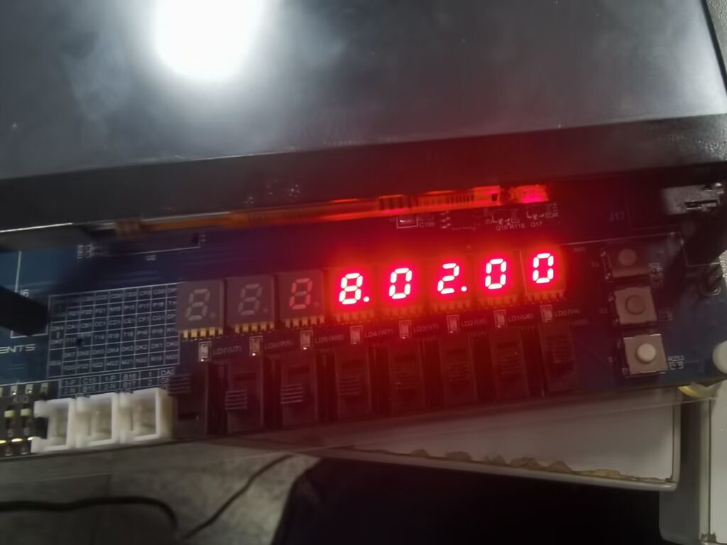
4. 实验结果
(可以使用综合后RTL图等实验过程截屏,实物照片等)

5. 实验中遇到的问题及解决方法
又又又一次一个变量在多个always块中赋值导致下板失败。解决办法为将多个always块合并为一个。
6. 实验感想和建议
数字钟的设计更多关注于顶层设计,比起流水灯的实验,模块更多且更为复杂,同时通过调用IP核来实现分频,但为了在有限的时间内完成实验内容,多个模块都没有关注内部的实现逻辑,例如数码管的段选,位选模块。而将精力集中在timing_module和control_module中。
The end
